LV08-01-I2C子系统-04-I2C驱动框架分析
来详细了解下I2C的驱动框架。若笔记中有错误或者不合适的地方,欢迎批评指正😃。
点击查看使用工具及版本
| PC端开发环境 | Windows | Windows11 |
| Ubuntu | Ubuntu20.04.2的64位版本 | |
| VMware® Workstation 17 Pro | 17.6.0 build-24238078 | |
| 终端软件 | MobaXterm(Professional Edition v23.0 Build 5042 (license)) | |
| Win32DiskImager | Win32DiskImager v1.0 | |
| Linux开发板环境 | Linux开发板 | 正点原子 i.MX6ULL Linux 阿尔法开发板 |
| uboot | NXP官方提供的uboot,使用的uboot版本为U-Boot 2019.04 | |
| linux内核 | linux-4.19.71(NXP官方提供) |
点击查看本文参考资料
| 分类 | 网址 | 说明 |
| 官方网站 | https://www.arm.com/ | ARM官方网站,在这里我们可以找到Cotex-Mx以及ARMVx的一些文档 |
| https://www.nxp.com.cn/ | NXP官方网站 | |
| https://www.nxpic.org.cn/ | NXP 官方社区 | |
| https://u-boot.readthedocs.io/en/latest/ | u-boot官网 | |
| https://www.kernel.org/ | linux内核官网 |
点击查看相关文件下载
| 分类 | 网址 | 说明 |
| NXP | https://github.com/nxp-imx | NXP imx开发资源GitHub组织,里边会有u-boot和linux内核的仓库 |
| nxp-imx/linux-imx/releases/tag/v4.19.71 | NXP linux内核仓库tags中的v4.19.71 | |
| nxp-imx/uboot-imx/releases/tag/rel_imx_4.19.35_1.1.0 | NXP u-boot仓库tags中的rel_imx_4.19.35_1.1.0 | |
| I.MX6ULL | i.MX 6ULL Applications Processors for Industrial Products | I.MX6ULL 芯片手册(datasheet,可以在线查看) |
| i.MX 6ULL Applications ProcessorReference Manual | I.MX6ULL 参考手册(下载后才能查看,需要登录NXP官网) | |
| Source Code | https://elixir.bootlin.com/linux/latest/source | linux kernel源码 |
| kernel/git/stable/linux.git - Linux kernel stable tree | linux kernel源码(官网,tag 4.19.71) | |
| https://elixir.bootlin.com/u-boot/latest/source | uboot源码 |
一、I2C设备驱动分析
1. 注册i2c_driver
1.1 注册I2C设备驱动
对于我们 I2C 设备驱动编写人来说,重点工作就是创建 i2c_driver,创建完成以后需要向Linux 内核注册这个 i2c_driver。i2c_driver 注册函数为 i2c_register_driver() :
1 | int i2c_register_driver(struct module *owner, struct i2c_driver *driver); |
其中owner 一般为 THIS_MODULE,driver是要注册的 i2c_driver。返回值: 0,成功;负值,失败。
另外 i2c_add_driver() 也常常用于注册 i2c_driver, i2c_add_driver() 是一个宏,定义如下:
1 | /* use a define to avoid include chaining to get THIS_MODULE */ |
其实i2c_add_driver 就是对 i2c_register_driver 做了一个简单的封装,只有一个参数,就是要注册的 i2c_driver。
1.2 销毁I2C设备驱动
注销 I2C 设备驱动的时候需要将前面注册的 i2c_driver 从 Linux 内核中注销掉,需要用到i2c_del_driver() 函数 :
1 | void i2c_del_driver(struct i2c_driver *driver) |
1.3 i2c_driver结构体注册示例
分配、设置、注册一个i2c_driver结构体:
1 | /* 传统匹配方式 ID 列表 */ |
可以在在ap3216c_probe函数中,分配、设置、注册file_operations结构体。在file_operations的函数中,使用i2c_transfer等函数发起I2C传输。
1.4 i2c_driver驱动框架
1 | // (1)第一部分 实现设备的读、写 和初始化等相关功能 |
1.5 在sysfs中的体现
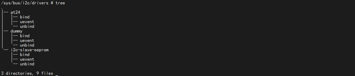
当我们加载了i2c设备驱动后,可以看一下这个 /sys/bus/i2c/drivers/目录,这个目录下存放着所有的i2c驱动:
2. 注册i2c_client
i2c_client表示一个I2C设备,那么我们怎么注册一个 i2c_client?这部分可以看instantiating-devices - Documentation/i2c/instantiating-devices
2.1 方式一
2.1.1 通过devicetree声明I2C设备
使用设备树的时候 I2C 设备信息通过创建相应的节点就行了,比如 NXP 官方的 EVK 开发板在 I2C1 上接了 mag3110 这个磁力计芯片,因此必须在 i2c1 节点下创建 mag3110 子节点,然后在这个子节点内描述 mag3110 这个芯片的相关信息。我们打开imx6ul-14x14-evk.dtsi ,找到以下内容:
1 | &i2c1 { |
第 7~11 行,向 i2c1 添加 mag3110 子节点,第 7 行“mag3110@0e”是子节点名字,“@”后面的“0e”就是 mag3110 的 I2C 器件地址。第 8 行设置 compatible 属性值为“fsl,mag3110”。第 9 行的 reg 属性也是设置 mag3110 的器件地址的,因此值为 0x0e。
I2C 设备节点的创建重点是 compatible 属性和 reg 属性的设置,一个用于匹配驱动,一个用于设置器件地址。
示例如下:
1 | i2c1: i2c@400a0000 { |
2.1.2 根据总线号声明I2C设备
首先肯定要描述 I2C 设备节点信息,在未使用设备树的时候需要在 BSP 里面使用 struct i2c_board_info 结构体来描述一个具体的 I2C 设备。
1 | struct i2c_board_info { |
type 和 addr 这两个成员变量是必须要设置的,一个是 I2C 设备的名字,一个是 I2C 设备的器件地址。我们看一下mach-pcm037.c这个文件中,就有这种用法:
1 | static struct i2c_board_info pcm037_i2c_devices[] = { |
中使用 I2C_BOARD_INFO 来完成 pcm037_i2c_devices 的初始化工作, I2C_BOARD_INFO 是一个宏,定义如下:
1 |
可以看出, I2C_BOARD_INFO 宏其实就是设置 i2c_board_info 的 type 和 addr 这两个成员变量,因此前面的主要工作就是设置 I2C 设备名字为 24c32, 24c32的器件地址为 0X52。可以在 Linux 源码里面全局搜索 i2c_board_info,会找到大量以 i2c_board_info 定义的I2C 设备信息,这些就是未使用设备树的时候 I2C 设备的描述方式,当采用了设备树以后就不会再使用 i2c_board_info 来描述 I2C 设备了。
上面的变量只是定义一个全局变量,然后需要通过i2c_register_board_info()函数创建一个i2c设备,我们来看一下:
1 | int i2c_register_board_info(int busnum, struct i2c_board_info const *info, unsigned len) |
示例如下:
1 | static void __init omap_h4_init(void) |
2.2 方式二:显式地实例化设备
有时候无法知道该设备挂载哪个I2C bus下,无法知道它对应的I2C bus number。但是可以通过其他方法知道对应的i2c_adapter结构体。可以使用下面两个函数来创建i2c_client。
2.2.1 i2c_new_device()
i2c_new_device()函数定义如下:
1 | struct i2c_client * |
i2c_new_device()函数会创建i2c_client,即使该设备并不存在。这里就不详细分析这个函数了,了解一下,示例如下:
1 | static struct i2c_board_info sfe4001_hwmon_info = { |
2.2.2 i2c_new_probed_device()
还可以使用i2c_new_probed_device()函数,函数定义如下:
1 | struct i2c_client * |
这个函数成功的话,会创建i2c_client,并且表示这个设备肯定存在。I2C设备的地址可能发生变化,比如AT24C02的引脚A2A1A0电平不一样时,设备地址就不一样。它可以罗列出可能的地址,i2c_new_probed_device()将会使用这些地址判断设备是否存在。这里也是简单了解下,示例如下:
1 | static const unsigned short normal_i2c[] = { 0x2c, 0x2d, I2C_CLIENT_END }; |
2.3 方式三:探测特定设备的I2C总线
由i2c_driver.detect函数来判断是否有对应的I2C设备并生成i2c_client。好像不是很建议使用这种方式,这个详细的可以看instantiating-devices - Method 3: Probe an I2C bus for certain devices。
2.4 方式四:从用户空间实例化
一般来说,内核应该知道连接了哪些I2C设备以及它们所在的地址。但是,在某些情况下,它不会这样做,因此添加了sysfs接口来让用户提供信息。该接口由2个属性文件组成,它们在每个I2C总线目录中创建:new_device和delete_device。这两个文件都只能写,我们必须向它们写入正确的参数,以便正确地实例化(或者删除)I2C设备。
- 文件new_device接受2个参数:I2C设备的名称(一个字符串)和I2C设备的地址(一个数字,通常以0x开头的十六进制表示,但也可以用十进制表示)。我们创建一个i2c_client, .name = “sdeveeprom”, .addr=0x50, .adapter是i2c-1
1 | echo sdeveeprom 0x50 > /sys/bus/i2c/devices/i2c-1/new_device |

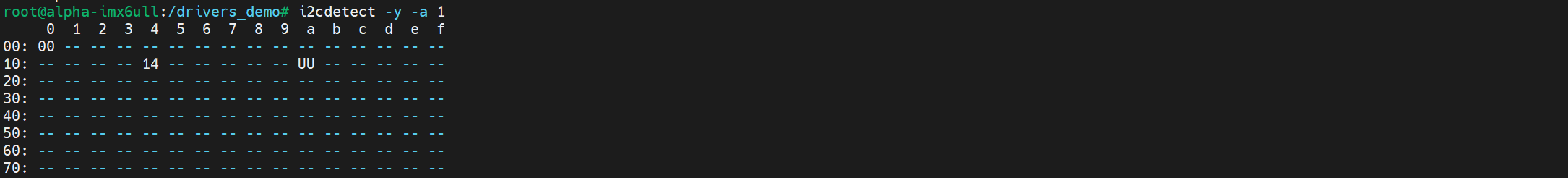
这个时候我们用i2cdetect工具看一下:
1 | i2cdetect -y -a 1 |
会发现什么也没有,这个应该是因为我们实际并没有对应的i2c设备存在,这就会导致i2cdetect向这个地址发数据的时候,并不会收到回应,所以就探测不出来了
- 文件delete_device接受一个参数:I2C设备的地址。由于没有两个设备可以在给定的I2C段上使用相同的地址,因此地址足以唯一地标识要删除的设备。删除一个i2c_client
1 | echo 0x50 > /sys/bus/i2c/devices/i2c-1/delete_device |

2.5 i2c_client设备注册示例
这里采用设备树的方式,以正点原子alpha开发板上的ap3216c为例,我们可以看一下原理图:
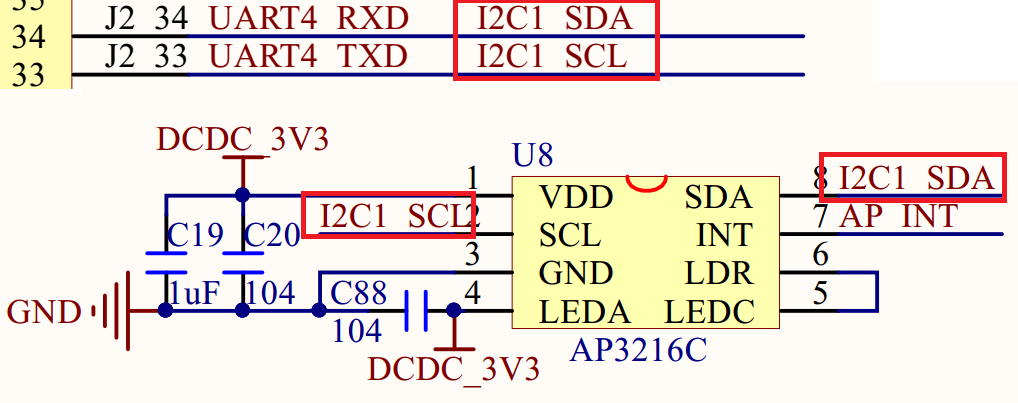
可以看到,AP3216C芯片的SCL和SDA是接在I2C1上的。
1 | &i2c1 { |
这两个引脚可以用作GPIO吗?我们可以看一下它们两个用的是什么引脚,看一下《 i.MX 6ULL Applications Processor Reference Manual》——Table 31-1. I2C External Signals :
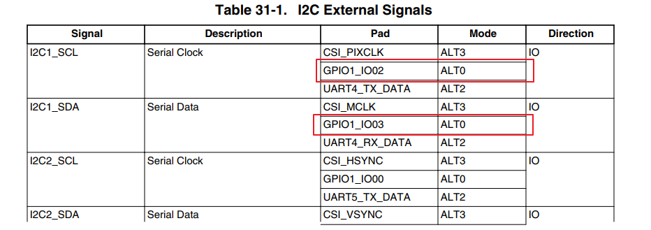
可以看到其实这两个引脚可以由GPIO1_IO02和GPIO1_03复用而来,从表上看,这两个gpio默认的功能就是I2C1的SCL和SDA。我们可以打开 imx6ul-14x14-evk.dtsi 找一下pinctrl_i2c1:
1 | pinctrl_i2c1: i2c1grp { |
可以发现,这里的I2C1用的是UART4的那两个引脚复用而来的。
2.6 在sysfs中的体现
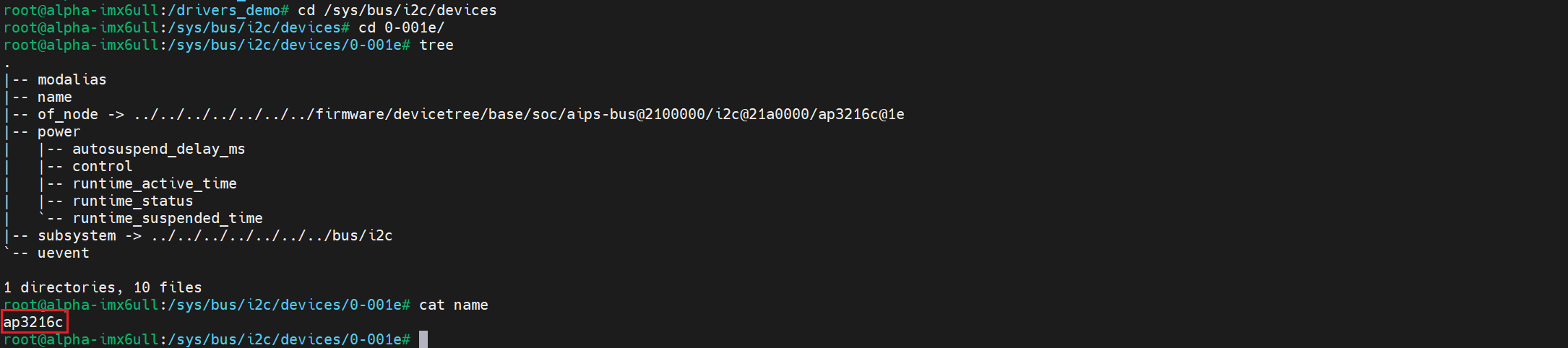
当我们在设备树写好设备节点后,可以看一下这个 /sys/bus/i2c/devices 目录,这个目录下存放着所有的i2c设备。如果设备树修改正确的话,会在/sys/bus/i2c/devices 目录下看到一个名为“0-001e”的子目录 :

“0-001e”就是 ap3216c 的设备目录,“1e”就是 ap3216c 器件地址。进入0-001e 目录,可以看到“name”文件, name 文件就保存着此设备名字,在这里就是“ap3216c” :
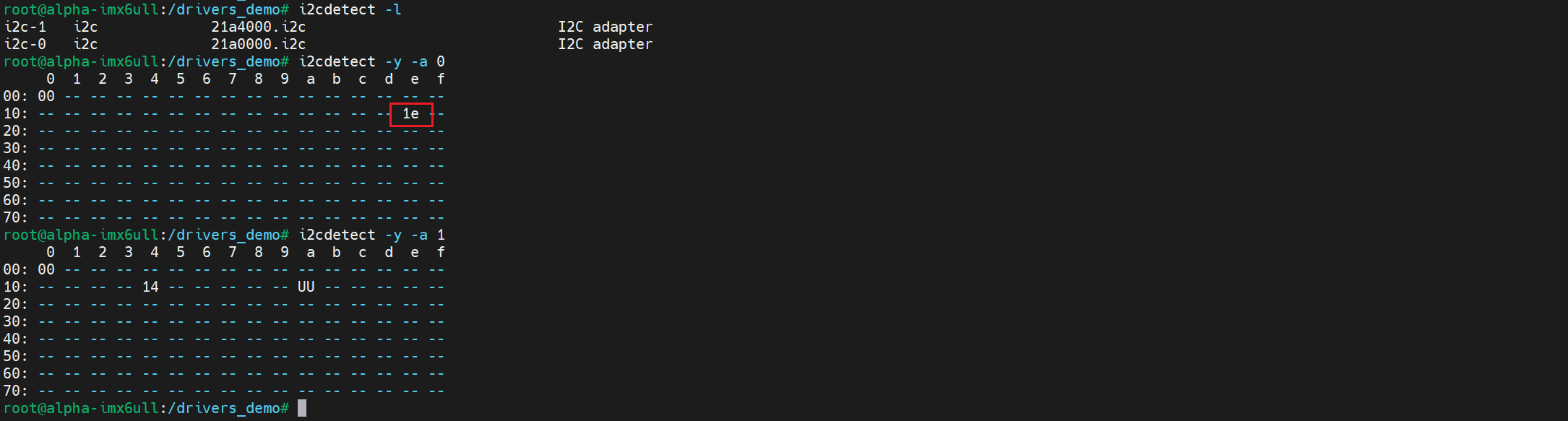
我们还可以用i2cdetect工具探测一下:
1 | i2cdetect -y -a 0 |
3. I2C设备和驱动的匹配
设备和驱动的匹配过程也是由 I2C 总线完成的, I2C 总线的数据结构为 i2c_bus_type:
1 | struct bus_type i2c_bus_type = { |
.match 就是 I2C 总线的设备和驱动匹配函数,在这里就是 i2c_device_match() 这个函数 :
1 | static int i2c_device_match(struct device *dev, struct device_driver *drv) |
3.1 设备树匹配:i2c_of_match_device()
第一种方式是通过函数i2c_of_match_device()完成设备树匹配:
1 | const struct of_device_id |
在这个函数中,调用了两个函数,这两个函数都是使用i2c_driver.driver.of_match_table这个匹配表进行匹配。
1 | const struct of_device_id *of_match_device(const struct of_device_id *matches, |
设备树中,某个I2C控制器节点下可以创建I2C设备的节点。如果I2C设备节点的compatible属性跟of_match_table的某项兼容,则匹配成功。
1 | static const struct of_device_id* |
这个函数是比较i2c_client.name跟某个i2c_driver.driver.of_match_table[i].compatible值,若有相同的,则匹配成功。(这种方式在platform平台总线中好像没看到,但是i2c中是有这样的方式的)。strchr()函数是用于在字符串中查找第一次出现的指定字符,并返回一个指向该字符的指针。如果未找到字符,则返回NULL。
3.2 id匹配:i2c_match_id()
1 | const struct i2c_device_id *i2c_match_id(const struct i2c_device_id *id, |
这个函数用于传统的、无设备树的 I2C 设备和驱动匹配过程。 使用i2c_driver.id_table来判断,当i2c_client.name 跟某个 i2c_driver.id_table[i].name 值相同,则匹配成功
i2c_driver跟i2c_client匹配成功后,就调用i2c_driver.probe函数。
4. I2C设备收发数据
4.1 i2c_transfer()
I2C 设备驱动首先要做的就是初始化 i2c_driver 并向 Linux 内核注册。当设备和驱动匹配以后 i2c_driver 里面的 probe 函数就会执行, probe 函数里面所做的就是字符设备驱动那一套了。
一般需要在 probe 函数里面初始化 I2C 设备,初始化完肯定就是对I2C设备进行操作了,在linux中为我们提供了 i2c_transfer() 函数。 i2c_transfer 函数最终会调用 I2C 适配器中 i2c_algorithm 里面的 master_xfer() 函数,对于imx6ull来说就是i2c_imx_algo.i2c_imx_xfer(),这个函数后面会进行分析,在里面就是完成了起始信号、结束信号、应答与非应答,读写等相关操作。
1 | int i2c_transfer(struct i2c_adapter *adap, struct i2c_msg *msgs, int num) |
函数参数
- adap: 所使用的 I2C 适配器, i2c_client 会保存其对应的 i2c_adapter。
- msgs: struct i2c_msg类型指针,表示I2C 要发送的一个或多个消息。
- num: 消息数量,也就是 msgs 的数量。
返回值: 负值,失败,其他非负值,发送的 msgs 数量。
另外还有两个API函数i2c_master_send()和i2c_master_recv(),分别用于I2C数据的收发操作,这两个函数最终都会调用i2c_transfer。就相当于替我们封装了一下,这样就可以不用自己去定义i2c_msg了。
4.2 收发示例
4.2.1 设备结构体
1 | /* 设备结构体 */ |
设备结构体,在设备结构体里面添加一个执行void的指针成员变量private_data,此成员变量用于保存设备的私有数据。在 I2C 设备驱动中我们一般将其指向 I2C 设备对应的i2c_client。
4.2.2 xxx_read_regs()
1 | /** |
该函数用于读取 I2C 设备多个寄存器数据。
第 12 行:定义了一个i2c_msg 数组, 2 个数组元素,因为 I2C 读取数据的时候要先发送要读取的寄存器地址,然后再读取数据,所以需要准备两个 i2c_msg。一个用于发送寄存器地址,一个用于读取寄存器值。
第15 - 19 行:对于 msg[0],将 flags 设置为 0,表示写数据。 msg[0]的 addr 是 I2C 设备的器件地址, msg[0]的 buf成员变量就是要读取的寄存器地址。
第 21 - 25 行:对于 msg[1],将 flags 设置为 I2C_M_RD,表示读取数据。msg[1]的 buf 成员变量用于保存读取到的数据, len 成员变量就是要读取的数据长度。
第26 - 34 行:调用i2c_transfer 函数完成 I2C 数据读操作。
4.2.3 xxx_write_regs()
1 | /** |
该函数用于向 I2C 设备多个寄存器写数据, I2C 写操作要比读操作简单一点,因此一个 i2c_msg 即可。
第 11 行:数组 b 用于存放寄存器首地址和要发送的数据。
第 18 行:设置 msg 的 addr 为 I2C 器件地址。
第 19 行:设置 msg 的 flags 为 0,也就是写数据。
第 21 行:设置要发送的数据,也就是数组 b。
第 22 行:设置 msg 的 len 为 len+1,因为要加上一个字节的寄存器地址。
第 24 行:最后通过 i2c_transfer 函数完成向 I2C 设备的写操作。
5. ap3216c实例
5.1 demo源码
demo源码可以看这里:30_i2c_subsystem/01_ap3216c · 苏木/imx6ull-driver-demo - 码云 - 开源中国
5.2 开发板测试
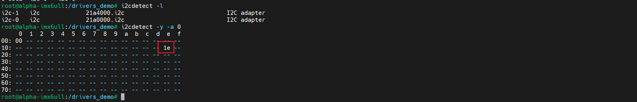
我们更新对应的设备树,然后重启,就会发现在/sys/bus/i2c/devices/下存在我们创建的ap3216c设备:

由于这设备室真实存在的,我们使用i2cdetect也会得到正确的回应:
1 | i2cdetect -y -a 0 |
然后加载驱动:
1 | insmod sdriver_ap3216c.ko |
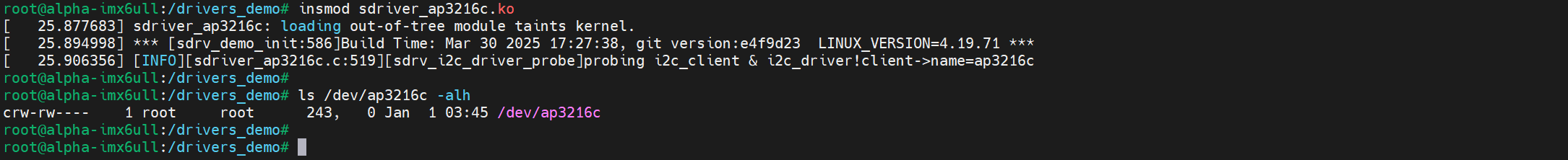
然后我们执行测试程序:
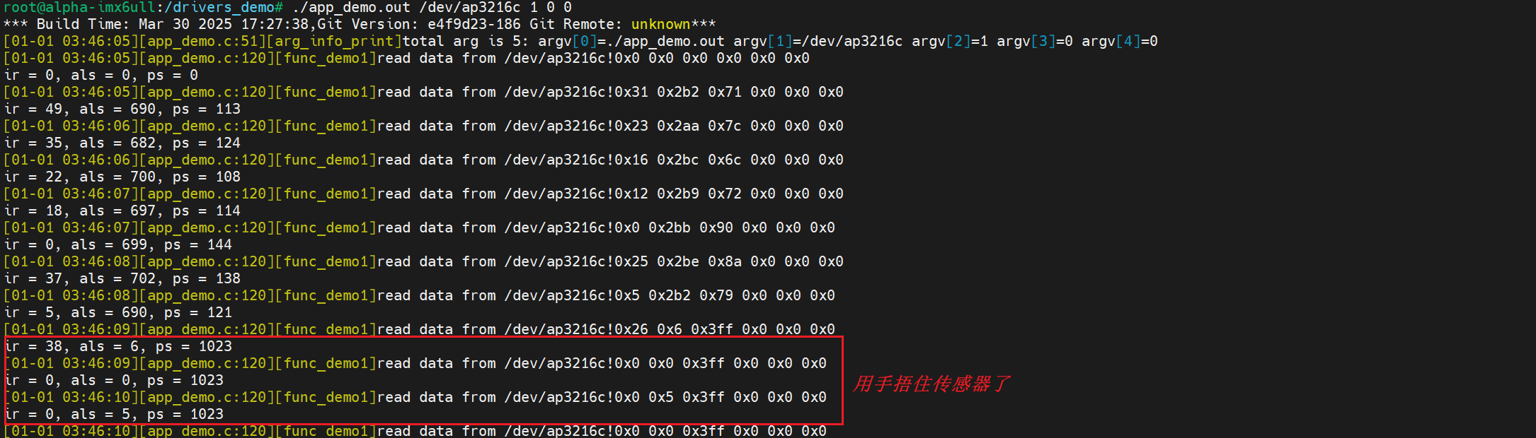
二、I2C总线驱动分析
I2C总线驱动其实就是I2C 适配器驱动,也就是 SOC 的 I2C 控制器驱动。就相当于之前在裸机上控制I.MX6U的物理I2C外设。
I2C 设备驱动是需要用户根据不同的 I2C 设备去编写,而 I2C 适配器驱动一般都是 SOC 厂商去编写的,比如 NXP 就编写好了 I.MX6U 的I2C 适配器驱动。
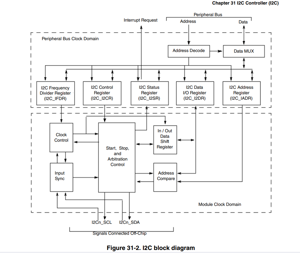
1. I.MX6U I2C 简介
可以参考《i.MX 6ULL Applications Processor Reference Manual》——Chapter 31 I2C Controller (I2C)
I.MX6U 提供了 4 个 I2C 外设,通过这四个 I2C 外设即可完成与 I2C 从器件进行通信。I.MX6U 的 I2C 支持两种模式:标准模式和快速模式,标准模式下 I2C 数据传输速率最高是 100Kbits/s,在快速模式下数据传输速率最高为 400Kbits/s。它的内部框图如下:
1.1 I2Cx_IADR(x=1~4)
这个可以看《 i.MX 6ULL Applications Processor Reference Manual》—— 31.7.1 I2C Address Register (I2Cx_IADR) :
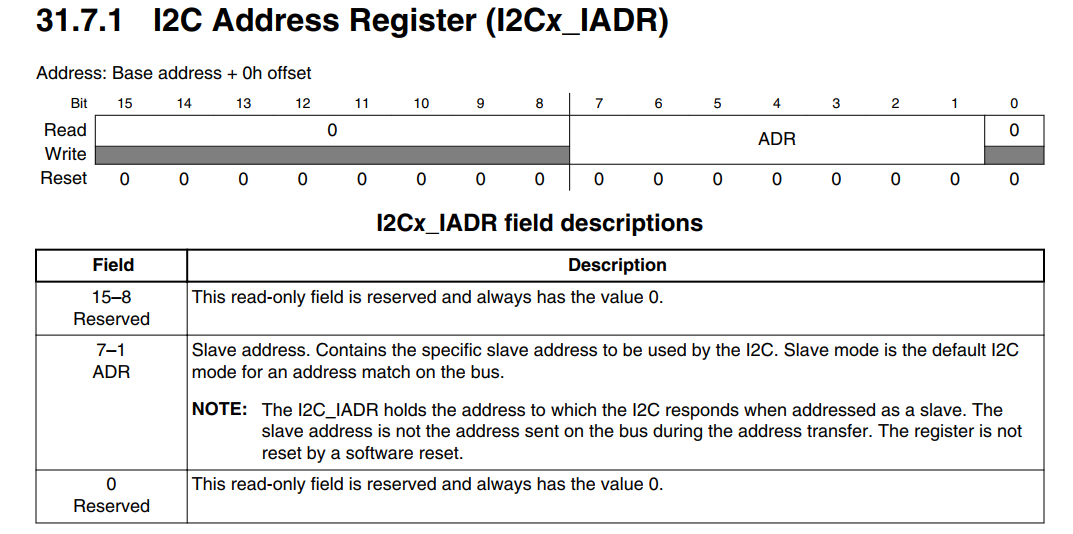
寄存器 I2Cx_IADR 只有 ADR(bit7:1)位有效,用来保存 I2C 从设备地址数据。当我们要访问某个 I2C 从设备的时候就需要将其设备地址写入到 ADR 里面。
1.2 I2Cx_IFDR (x=1~4)
这个可以看《 i.MX 6ULL Applications Processor Reference Manual》—— 31.7.2 I2C Frequency Divider Register (I2Cx_IFDR) :
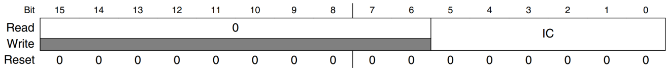
这个是 I2C 的分频寄存器,寄存器 I2Cx_IFDR 也只有 IC(bit5:0)这个位,用来设置 I2C 的波特率, I2C 的时钟源可以选择 IPG_CLK_ROOT=66MHz,通过设置 IC 位既可以得到想要的 I2C 波特率。 IC 位可选的设置可以看《 i.MX 6ULL Applications Processor Reference Manual》—— Table 31-3. I2C_IFDR Register Field Values 。
不像其他外设的分频设置一样可以随意设置, Table 31-3. I2C_IFDR Register Field Values 中列出了 IC 的所有可选值。比如现在I2C的时钟源为66MHz,我们要设置I2C的波特率为100KHz,那么IC就可以设置为0X15,也就是 640 分频。 66000000/640=103.125KHz ≈ 100KHz。
1.3 I2Cx_I2CR (x=1~4)
这个可以看《 i.MX 6ULL Applications Processor Reference Manual》—— 31.7.3 I2C Control Register (I2Cx_I2CR),这个是 I2C 控制寄存器:
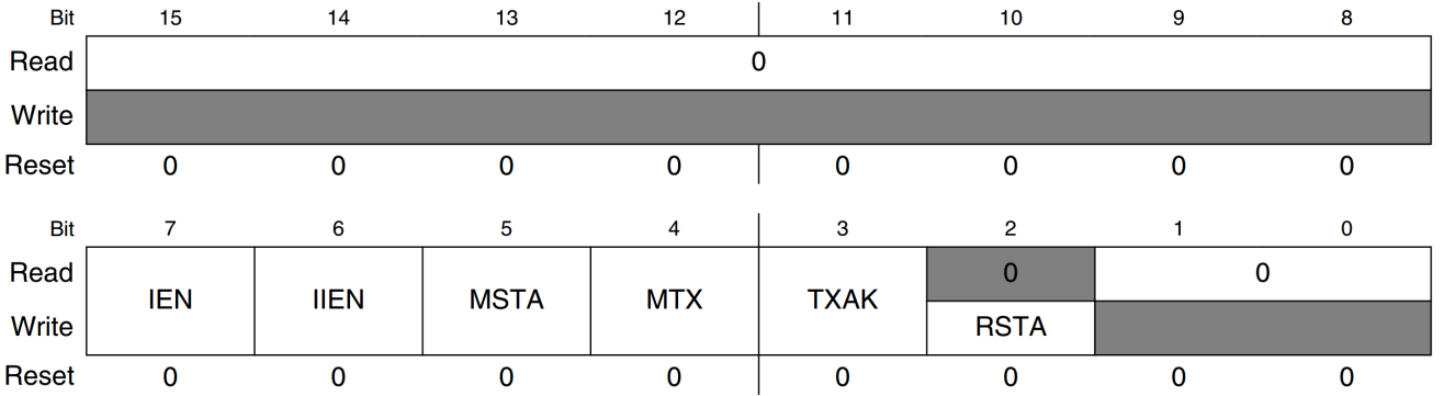
存器 I2Cx_I2CR 的各位含义如下:
IEN(bit7): I2C 使能位,为 1 的时候使能 I2C,为 0 的时候关闭 I2C。
IIEN(bit6): I2C 中断使能位,为 1 的时候使能 I2C 中断,为 0 的时候关闭 I2C 中断。
MSTA(bit5):主从模式选择位,设置 IIC 工作在主模式还是从模式,为 1 的时候工作在主模式,为 0 的时候工作在从模式。
MTX(bit4):传输方向选择位,用来设置是进行发送还是接收,为 0 的时候是接收,为 1 的时候是发送。
TXAK(bit3):传输应答位使能,为 0 的话发送 ACK 信号,为 1 的话发送 NO ACK 信号。
RSTA(bit2):重复开始信号,为 1 的话产生一个重新开始信号。
1.4 I2Cx_I2SR (x=1~4)
这个可以看《 i.MX 6ULL Applications Processor Reference Manual》—— 31.7.4 I2C Status Register (I2Cx_I2SR) ,这个是 I2C 的状态寄存器 :
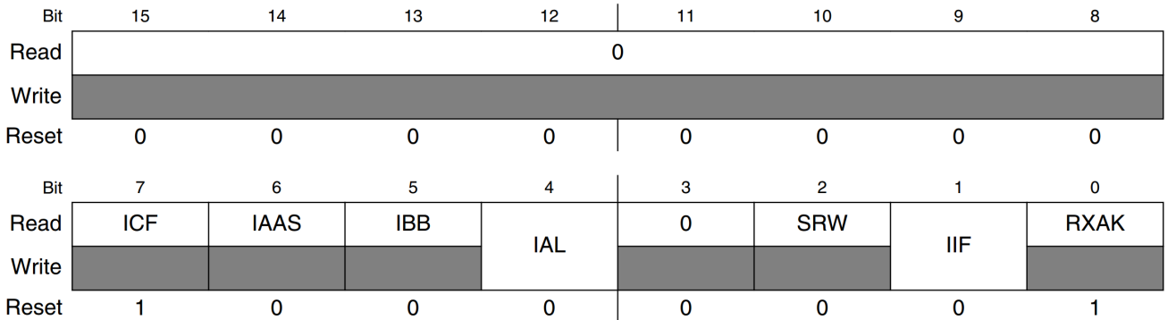
寄存器 I2Cx_I2SR 的各位含义如下:
- ICF(bit7):数据传输状态位,为 0 的时候表示数据正在传输,为 1 的时候表示数据传输完成。
- IAAS(bit6):当为 1 的时候表示 I2C 地址,也就是 I2Cx_IADR 寄存器中的地址是从设备地址。
- IBB(bit5): I2C 总线忙标志位,当为 0 的时候表示 I2C 总线空闲,为 1 的时候表示 I2C 总线忙。
- IAL(bit4):仲裁丢失位,为 1 的时候表示发生仲裁丢失。
- SRW(bit2):从机读写状态位,当 I2C 作为从机的时候使用,此位用来表明主机发送给从机的是读还是写命令。为 0 的时候表示主机要向从机写数据,为 1 的时候表示主机要从从机读取数据。
- IIF(bit1): I2C 中断挂起标志位,当为 1 的时候表示有中断挂起,此位需要软件清零。
- RXAK(bit0): 应答信号标志位,为 0 的时候表示接收到 ACK 应答信号,为 1 的话表示检测到 NO ACK 信号。
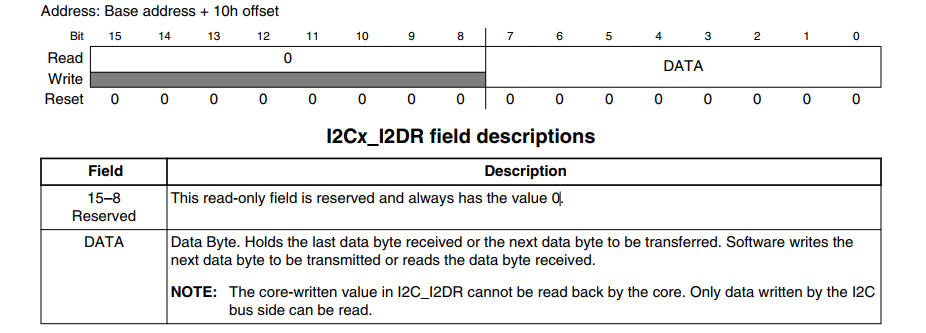
1.5 I2Cx_I2DR (x=1~4)
这个可以看《 i.MX 6ULL Applications Processor Reference Manual》—— 31.7.5 I2C Data I/O Register (I2Cx_I2DR) ,这是 I2C 的数据寄存器,此寄存器只有低 8 位有效,当要发送数据的时候将要发送的数据写入到此寄存器,如果要接收数据的话直接读取此寄存器即可得到接收到的数据。
①、与标准 I2C 总线兼容。
②、多主机运行
③、软件可编程的 64 中不同的串行时钟序列。
④、软件可选择的应答位。⑤、开始/结束信号生成和检测。⑥、重复开始信号生成。⑦、确认位生成。⑧、总线忙检测
2. I2C1 控制器节点
在 imx6ul.dtsi 文件中找到 I.MX6U 的 I2C1 控制器节点,节点内容如下所示:
1 | i2c1: i2c@21a0000 { |
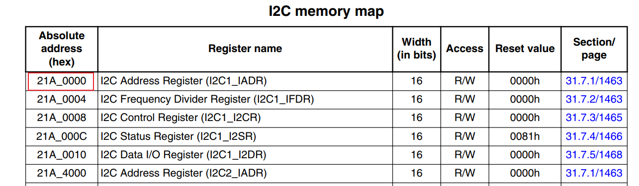
可以看到,I2C1的起始地址就是0x021A_0000。不过这里重点关注 i2c1 节点的 compatible 属性值,因为通过 compatible 属性值可以在 Linux 源码里面找到对应的驱动文件。
这里i2c1节点的compatible属性值有两个:“fsl,imx6ul-i2c”和“fsl,imx21- i2c”,在 Linux 源码中搜索这两个字符串即可找到对应的驱动文件。
3. I2C适配器驱动
我们打开 i2c-imx.c - drivers/i2c/busses/i2c-imx.c文件,找到这些内容:
1 | static struct platform_driver i2c_imx_driver = { |
这部分是驱动的入口和退出函数,可以看到I.MX6U 的 I2C 适配器驱动是个标准的 platform 驱动,由此可以看出,虽然 I2C 总线为别的设备提供了一种总线驱动框架,但是 I2C 适配器却是 platform驱动。
3.1 i2c_imx_driver.of_match_table
既然是platform平台总线驱动,那么就和前面肯定是一样的,我们先看一下 i2c_imx_driver.of_match_table,可以看到它的值是 i2c_imx_dt_ids :
1 | static const struct of_device_id i2c_imx_dt_ids[] = { |
这里就是和设备树进行匹配的匹配表啦,前面i2c1的属性 compatible :
1 | compatible = "fsl,imx6ul-i2c", "fsl,imx21-i2c"; |
所以这里就可以匹配上了。
3.2 i2c_imx_driver. i2c_imx_probe
按照platform平台总线的逻辑,当i2c适配器和驱动匹配后就会调用 i2c_imx_driver. i2c_imx_probe函数
1 | static int i2c_imx_probe(struct platform_device *pdev) |
i2c_imx_probe 函数主要的工作就是一下两点:①、初始化 i2c_adapter,设置 i2c_algorithm 为 i2c_imx_algo,最后向 Linux 内核注册i2c_adapter。②、初始化 I2C1 控制器的相关寄存器。
3.3 i2c_imx_algo
我们来看一下 i2c_imx_probe()函数的1084行:
1 | i2c_imx->adapter.algo = &i2c_imx_algo; |
这里是在设置 i2c_adapter的algo成员变量为 i2c_imx_algo ,也就是设置 i2c_algorithm。
1 | static const struct i2c_algorithm i2c_imx_algo = { |
前面我们就知道i2c_algorithm中的关键函数**i2c_algorithm.master_xfer()**用于产生i2c访问周期需要的start stop ack信号,以i2c_msg(即i2c消息)为单位发送和接收通信数据。在这里就对应 i2c_imx_algo.i2c_imx_xfer():
1 | static int i2c_imx_xfer(struct i2c_adapter *adapter, |
这里涉及到这几个函数:i2c_imx_start、 i2c_imx_read、 i2c_imx_write 和 i2c_imx_stop(),这里就是和裸机中i2c的驱动是一样的了,可以参考20_i2c/01_i2c_demo/bsp/i2c/bsp_i2c.c · 苏木/imx6ull-bare-demo - 码云 - 开源中国这个demo中的i2c外设的操作进行理解。不过这里都是物理I2C的操作,并不是用GPIO模拟的,所以都是在操作I2C外设相关寄存器。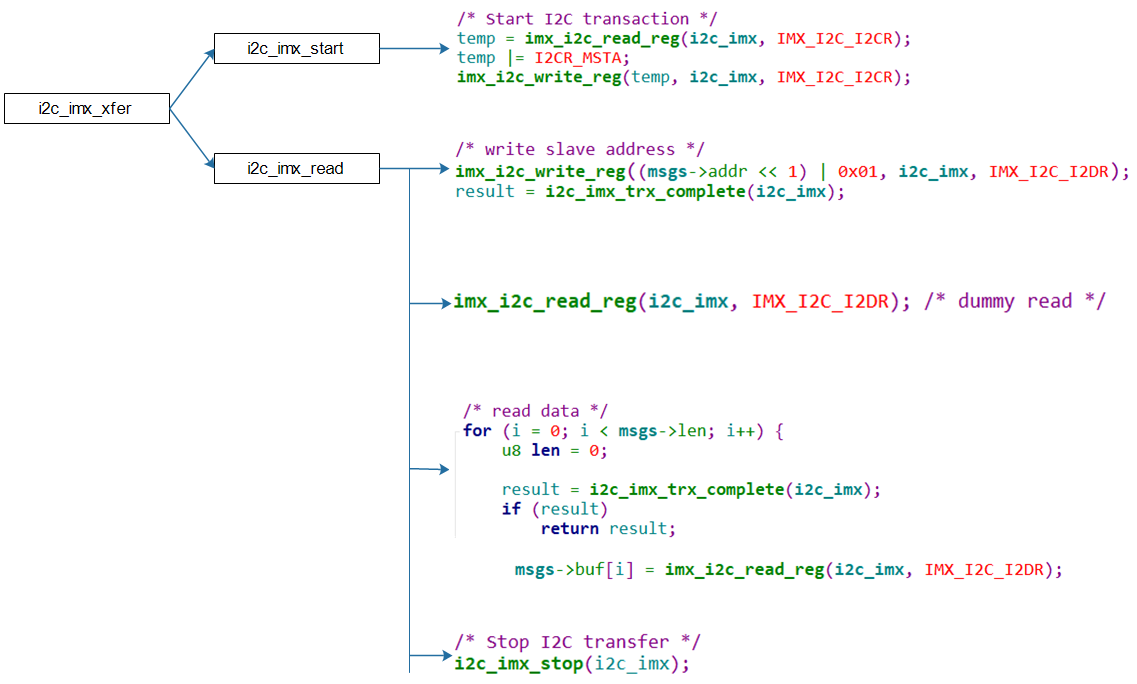
3.4 i2c_adapter注册/注销函数
3.4.1 i2c_add_adapter()
1 | int i2c_add_adapter(struct i2c_adapter *adapter) |
3.4.2 i2c_add_numbered_adapter()
1 | int i2c_add_numbered_adapter(struct i2c_adapter *adap) |
3.4.3 i2c_del_adapter()
1 | void i2c_del_adapter(struct i2c_adapter *adap) |
4. 编写一个虚拟的i2c_adapter
4.1 设备树
在设备树根节点里构造I2C Bus节点:
1 | / { |
这个其实就相当于i2c_adapter的设备。
4.2 适配器的驱动
4.2.1 要做哪些?
前面我们知道 I2C 适配器驱动是个标准的 platform 驱动,所以这里其实就按照 platform 驱动的编写流程,进行分配、设置、注册platform_driver结构体即可。核心是probe函数,它要做这几件事:
- 根据设备树信息设置硬件(引脚、时钟等)
- 分配、设置、注册i2c_apdater,i2c_apdater的核心是master_xfer函数,它的实现取决于硬件,大概代码如下
1 | static int xxx_master_xfer(struct i2c_adapter *adapter, |
4.2.2 i2c_adapter框架
框架代码可以看这里:30_i2c_subsystem/02_i2c_adapter_virtual/drivers_demo/sdriver_demo.c · 苏木/imx6ull-driver-demo - 码云 - 开源中国,更新设备树,然后加载驱动,我们用i2cdetect列出所有的i2c总线:
1 | i2cdetect -l |
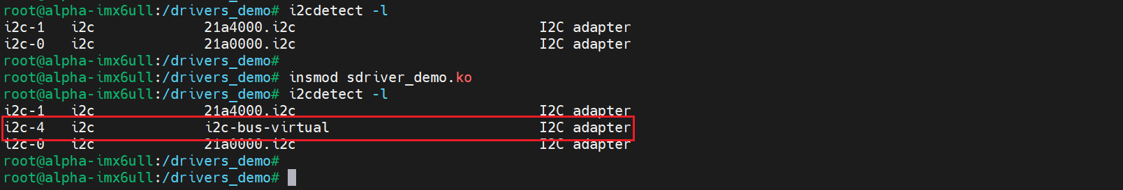
注意:不同的板子上,i2c-bus-virtual的总线号可能不一样,上问中总线号是4。
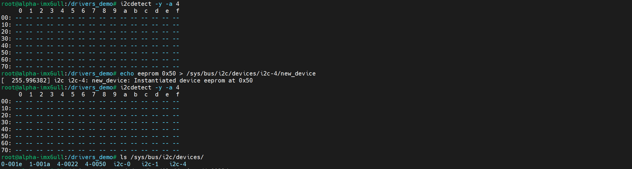
我们在这个总线上创建一个i2c设备:
1 | echo sdeveeprom 0x50 > /sys/bus/i2c/devices/i2c-4/new_device |

发现也是可以的。
4.2.3 模拟EEPROM
在前面完成的虚拟的I2C_Adapter驱动框架里,只要实现了其中的master_xfer函数,这个I2C Adapter就可以使用了。在master_xfer函数里,我们模拟一个EEPROM,思路如下:
- 分配一个512字节的buffer,表示EEPROM
- 对于slave address为0x50的i2c_msg,解析并处理
对于写:把i2c_msg的数据写入buffer。对于读:从buffer中把数据写入i2c_msg。
- 对于slave address为其他值的i2c_msg,返回错误
完整的demo看这里:30_i2c_subsystem/03_i2c_adapter_virtual_ok · 苏木/imx6ull-driver-demo - 码云 - 开源中国
4.3 模拟EEPROM demo
4.3.1 demo源码
demo源码看这里:30_i2c_subsystem/03_i2c_adapter_virtual_ok · 苏木/imx6ull-driver-demo - 码云 - 开源中国
4.3.2 测试结果
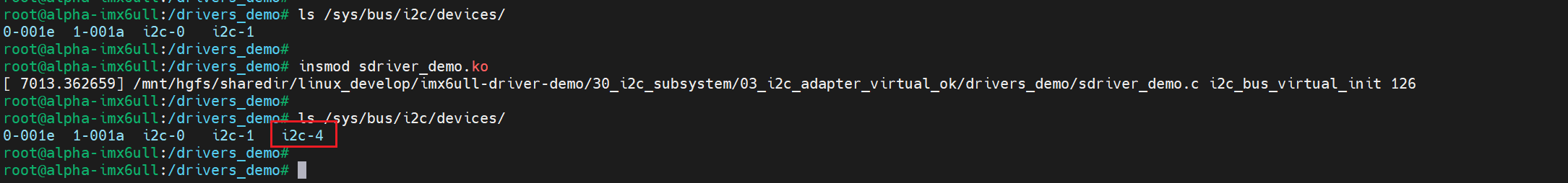
更新开发板中的设备树,然后应该可以i2c/devices/在看到对应的i2c适配器:
然后我们使用i2c-tools进行测试:
- 列出I2C总线
1 | i2cdetect -l |
结果类似下列的信息:

注意:不同的板子上,i2c-bus-virtual的总线号可能不一样,上问中总线号是4。
- 检查虚拟总线下的I2C设备
1 | 假设虚拟I2C BUS号为4 |
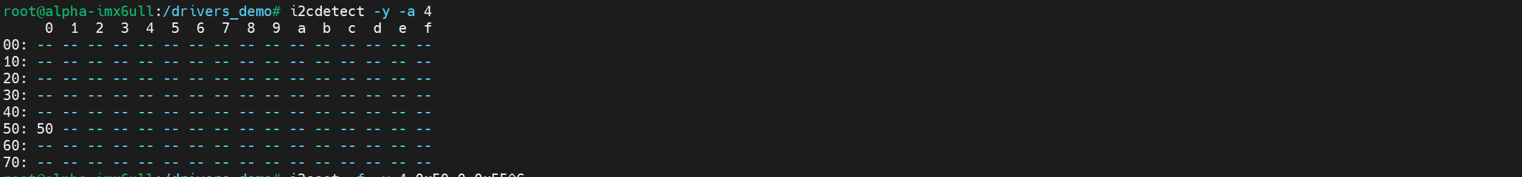
这里似乎并不需要自己创建设备。
- 读写模拟的EEPROM
1 | i2cset -f -y 4 0x50 0 0x55 # 假设虚拟I2C BUS号为4 往0地址写入0x55 |

三、GPIO模拟I2C
1. GPIO模拟I2C简介
在Linux项目中,如果出现硬件I2C不够用的情况,就可以使用模拟i2c来解决。其实I2C只是规定了数据传输的协议,并没有说一定要使用物理的I2C外设,我们知道2C协议信号如下:
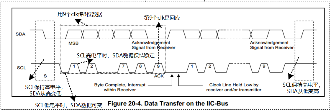
这里其实就是一根时钟线,一根数据线,这些我们完全可以用两个GPIO来进行模拟。之前学习单片机的时候其实一开始用的都是gpio模拟i2c:STM32_HAL_Prj/Drivers/BSP/IIC/myiic.c · 苏木/STM32F103-Prj - 码云 - 开源中国
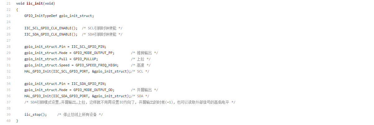
使用GPIO模拟I2C的要点:
- 引脚设为GPIO。
- GPIO设为输出、开极/开漏(open collector/open drain)。
- 要有上拉电阻,为什么需要上拉电阻,在前面已经学习过了,主要就是可以方便的实现数据双向传输。以及实现多个设备对I2C总线的使用。
2. GPIO引脚定义
既然是GPIO模拟I2C,那其实,只需要两个I2C就可以了,但是在不同版本的内核中,会支持一些新的写法。
1 | Example nodes: |
1 | i2c@0 { |
3. i2c-gpio基本框架
Lnux内核的i2c-gpio是使用GPIO模拟I2C协议的驱动,在内核中已经实现了,我们要做的只需要配置2个GPIO(SDA和SCL)即可。
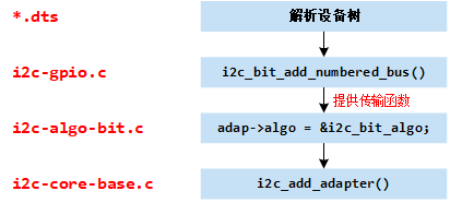
(1)解析设备树中的引脚配置信息
(2)提供GPIO SDA和SCL引脚配置接口。
(1)向I2C Core注册一个adapter
(2)提供I2C通信时的算法,然后通过i2c-gpio.c提供GPIO配置接口来收发数据。
注册成功后,
"i2c-dev"驱动就会自动创建对应的"/dev/i2c-x"字符设备,然后我们就可以在应用层和驱动层操作该总线。
4. 如何添加一个模拟I2C?
4.1 驱动相关文件放在那里?
GPIO模拟I2C协议的驱动位于 busses - drivers/i2c/busses 目录。驱动名称为“i2c-gpio”,驱动文件为i2c-gpio.c - drivers/i2c/busses/i2c-gpio.c,这个也是platform驱动:
4.2 使能内核的I2C GPIO驱动
我们在内核源码目录下输入:
1 | make ARCH=arm CROSS_COMPILE=arm-linux-gnueabihf- imx_v6_v7_defconfig |
按以下路径找到对应的配置项:
1 | Device Drivers-> |
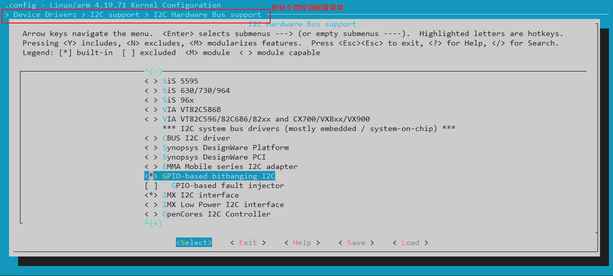
确认配置后,i2c-gpio相关驱动就会被编译进内核。当然我们也可以编译成驱动模块,然后手动加载,不过还是直接编译到内核更方便一些。
4.3 设备树配置
4.3.1 模拟I2C节点
i2c-gpio的i2c_adapter设备树节点这样写:
1 | i2c5:i2c5_gpio { |
我们打开imx6ul.dtsi添加以上内容,需要注意的是添加需要模拟i2c的gpio的时候,一定是先放sda再放scl,因为它是在i2c-gpio.c里面定义好的,必须这么写才可以。
4.3.2 修改aliases
这里以 imx6ul.dtsi - arch/arm/boot/dts/imx6ul.dtsi 为例,我们添加如下内容:
1 | / { |
为什么需要修改aliases呢?因为在添加添加adapter时,会通过aliases的别名编号配置adapter->nr总线编号。注册成功后,会创建/dev/i2c-4设备。在i2c_add_adapter()函数中:
1 | int i2c_add_adapter(struct i2c_adapter *adapter) |
这样在注册i2c_adapter的时候i2c_add_adapter()函数就会获取到对应的一个编号。
4.3.3 open drain属性
使用GPIO模拟I2C模式时,一般GPIO需要工作在开漏模式。在of_i2c_gpio_get_props()函数中,解析是否有定义open drain相关属性。如下:
1 | static void of_i2c_gpio_get_props(struct device_node *np, |
当定义i2c-gpio,sda-open-drain和i2c-gpio,scl-open-drain属性后,说明是其它子系统已经将该GPIO配置成开漏输出了,这里不再进行开漏的配置。如果dts里面不定义,就启动GPIOD_OUT_HIGH_OPEN_DRAIN配置GPIO,我们可以看一下i2c_gpio_probe():
1 | if (pdata->sda_is_open_drain) |
所以,这里可以不定义该属性,它将会在函数i2c_gpio_probe()中配置为开漏。
4.3.4 添加i2c设备
有了i2c适配器,就可以添加对应的i2c设备了,这里就和前面一样了。为了方便后面测试模拟I2C总线,这里还是需要一个设备:
1 | &i2c5 { |
不过,我们并没有实际的设备挂载在上面,后面可以直接用下面的命令创建模拟的i2c设备:
1 | // 创建一个i2c_client, .name = "eeprom", .addr=0x50, .adapter是i2c-4 |
4.3.5 开发板测试
我们更新开发板的设备树,就会发现这里新增了/dev/i2c-4总线设备,它就是我们新增的GPIO模拟I2C总线设备。

使用i2c_tools测试该总线,可以正常的识别到设备,说明移植已经成功了。但是我这里实际上并没有接入i2c设备,就算手动创建一个i2c设备,也只会创建对应的设备,但是i2cdetect不会有反应,因为我们实际并没有对应的i2c设备存在,这就会导致i2c向这个地址发数据的时候,并不会收到回应,所以就探测不出来了:
5. i2c-gpio驱动分析
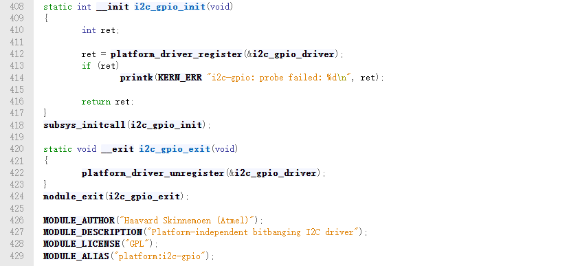
前面知道,GPIO模拟I2C协议的驱动位于 busses - drivers/i2c/busses 目录。驱动名称为“i2c-gpio”,驱动文件为i2c-gpio.c - drivers/i2c/busses/i2c-gpio.c,是一个平台设备驱动,它的平台设备驱动结构体为 i2c_gpio_driver
1 | static struct platform_driver i2c_gpio_driver = { |
5.1 i2c_gpio_driver.driver.of_match_table
先来看一下这个匹配表,对应的数组为 i2c_gpio_dt_ids
1 | static const struct of_device_id i2c_gpio_dt_ids[] = { |
所以我们前面定义的模拟I2C的compatible属性名称就包含的有”i2c-gpio”。
5.2 i2c_gpio_driver.probe
当i2c适配器设备和驱动匹配的时候,就会执行.probe函数,在这里就是i2c_gpio_probe()
1 | static int i2c_gpio_probe(struct platform_device *pdev) |
5.2.1 解析设备树
我们看一下这个 of_i2c_gpio_get_props()
1 | static void of_i2c_gpio_get_props(struct device_node *np, |
- i2c-gpio,delay-us:配置每个bit的使用时间,也就是I2C通信时Clock的频率。
- i2c-gpio,timeout-ms:配置i2c通信时的超时时间,如果超过这个时间没有收到ack,说明通信失败。
- i2c-gpio,sda-open-drain:是否有在其它子系统里面定义了sda gpio为开漏模式,如果有就定义该属性。
- i2c-gpio,scl-open-drain:是否有在其它子系统里面定义了scl gpio为开漏模式,如果有就定义该属性。
- i2c-gpio,scl-output-only:配置scl gpio只支持输出模式,不支持输入模式。
5.2.2 注册到i2c-algo-bit.c
我们看一下i2c_bit_add_numbered_bus():
1 | int i2c_bit_add_numbered_bus(struct i2c_adapter *adap) |
它调用的是__i2c_bit_add_busr()函数:
1 | static int __i2c_bit_add_bus(struct i2c_adapter *adap, |
可以看到这里为i2c-gpio添加了对应的 i2c_algorithm ,这里对应的是 i2c_bit_algo,它的master_xfer成员指向的函数就为模拟i2c添加用于产生i2c访问周期需要的start stop ack信号操作函数。就算我们自己写GPIO模拟I2C驱动,也都必须实现这些函数。
1 | const struct i2c_algorithm i2c_bit_algo = { |
这个我们后面再看。然后就是调用 add_adapter() 向I2C Core注册一个adapter,注册成功后,"i2c-dev"驱动就会自动创建对应的"/dev/i2c-x"字符设备,然后我们就可以在应用层和驱动层操作该总线。
5.3 i2c_bit_algo
5.3.1 i2c_bit_algo.functionality
i2c_bit_algo.functionality对应的函数是bit_func()
1 | static u32 bit_func(struct i2c_adapter *adap) |
这里就是返回支持的I2C协议。
5.3.2 i2c_bit_algo.master_xfer
i2c_bit_algo.master_xfer对应的是bit_xfer()函数,这个函数就是为i2c的访问产生i2c访问周期需要的start stop ack信号:
1 | static int bit_xfer(struct i2c_adapter *i2c_adap, |
当我们使用i2c_transfer() 函数收发数据的时候,就会调用到这个函数。
6. GPIO模拟I2Cdemo
6.1 demo源码
这个demo源码可以看这里:30_i2c_subsystem/04_i2c_gpio/device_tree/imx6ull-alpha-emmc/imx6ull-alpha-emmc.dtsi · 苏木/imx6ull-driver-demo - 码云 - 开源中国
这个demo主要是修改设备树,驱动是不需要的,另外还修改了kernel/dts_common/imx6ul.dtsi · 苏木/imx6ull-driver-demo - 码云 - 开源中国
6.2 开发板测试
就和这一节的4.3的测试现象一样。
参考资料:
【驱动】linux下I2C驱动架构全面分析 - Leo.cheng - 博客园
Linux i2c子系统(一) _动手写一个i2c设备驱动_Linux编程_Linux公社-Linux系统门户网站
I2C子系统–mpu6050驱动实验 野火嵌入式Linux驱动开发实战指南——基于i.MX6ULL系列 文档